How I wired my Instax Wide to develop... after my #instaxhack lens mod

Things don't get simpler than this. All I needed the switch to do is allow or not allow current from the battery to the positve + contact to the motor.
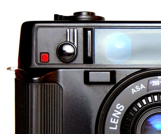
In the above photo, the red wire comes from the positive side of the battery case. The red wires goes to the GND contact on the switch circuit board. When you push the shutter release, the round contact on the, you turn the motor on.
It turns the motor on because the current goes through the red wire, through the switch, to the white wire, which is soldered to the SP contact on the switch circuit board.

That white wire, because it continues the flow of current from the red wire, leads to the positive contact on the electric motor in the picture below. The motor has the red painted dot which lets you know which contact on the motor should be positive.
After that all you have to do is take the negative wire (the black wire) that leads to the Negative side of the battery pack and solder it to the negative side of the motor.
That completes the circuit. The circuit breaks when you take your finger off the shutter release and closes, running the motor, when you push on the button.

Hold the button for about a five count or until the film clears and, I've discovered, the ejector which feeds the film into the rollers will be ready for the next MANUAL exposure.

Comments
- From a young photographer with love.
In the above photo, the red wire comes from the positive side of the battery case. The red wires goes to the GND contact on the switch circuit board. When you push the shutter release, the round contact on the, you turn the motor on.
please correct it, these details are important